Robot construction photos
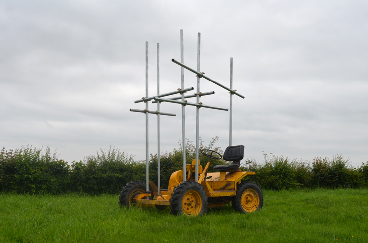
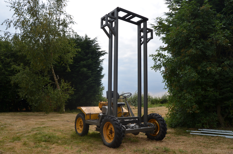
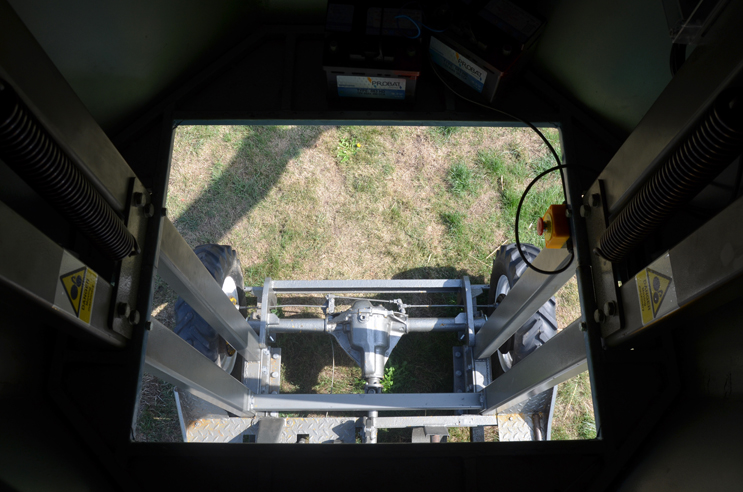
I'd wanted to make a garden-based robot for a while, but didn't really want to commit to mounting it on permanent concrete foundations. A 1978 Thwaites dumper made an ideal base, as it had a good solid chassis to bolt to, and the lack of suspension stops the structure from rocking around. It was also useful to know the front axle was rated to carry at least 1 tonne. And this meant of course that the robot would be relatively portable.
After procuring a dumper truck via the magic of eBay, the very first step was to attach some scaffolding and drive around, just to get a feel for how the dumper might behave with something mounted on top. While testing on a rainy afternoon, a sudden flash of lightning signalled it was time to stop sitting in a field under some metal poles.
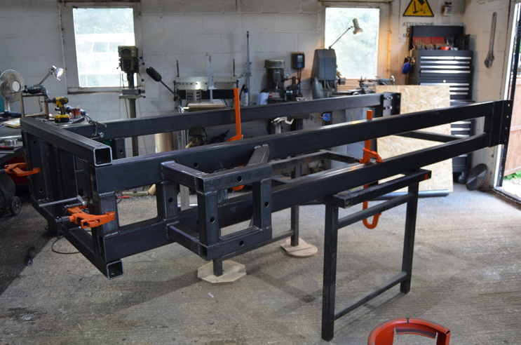
After removing the dumper bucket, some plates were welded to the chassis, to convert some of the channel to box section.
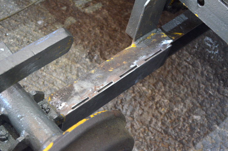
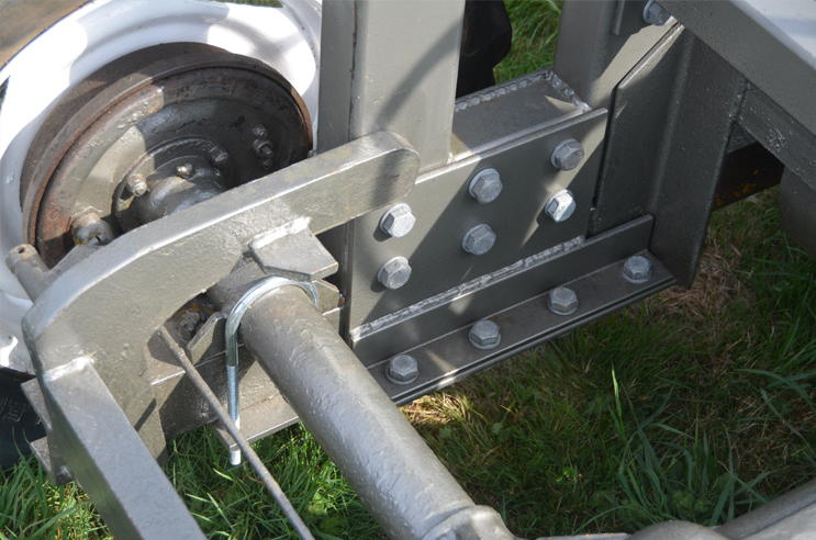
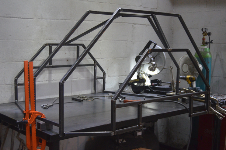
This formed the basis of the interface between the dumper and the robot's vertical steel 'legs'. A series of somewhat over-engineered plates were made to fit and bolted around the chassis.
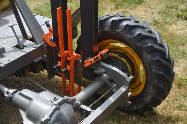
Some additional U-bolts were also fitted to strengthen the front axle. Although the robot only weighed around 650Kg, its height added leverage that might cause additional stresses when driving over bumps.
During the project I had been visiting Tim Hunkin to help out a little bit with his new arcade machine, "The Fulfilment Center". Some stepper motor stuff, but mostly drinking tea and chatting, which was immensely enjoyable.
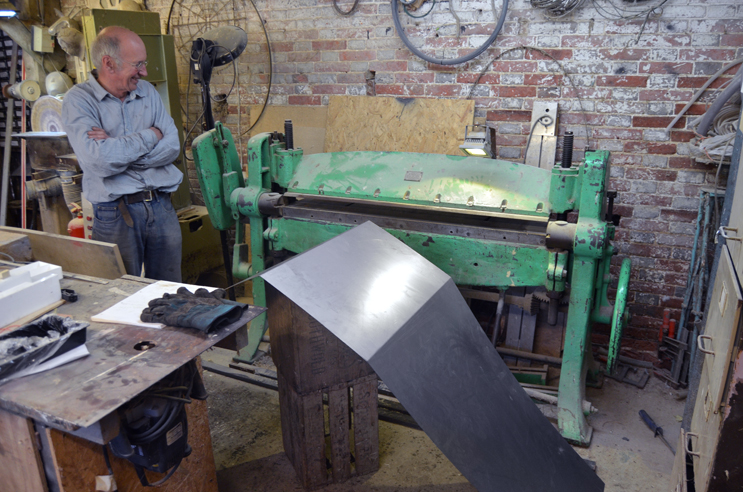
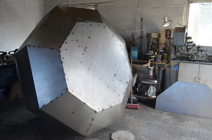
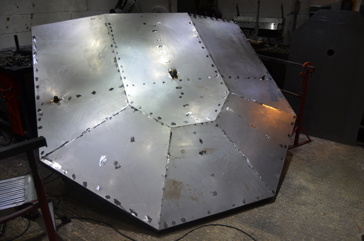
Tim has a magnificent folding machine that he kindly let me use to fold the panels for the robot. It's incredibly solid, with a weight on a lovely parallel linkage. I used a magnetic inclinometer to monitor the folding angle, and a plywood former to double check the shape.
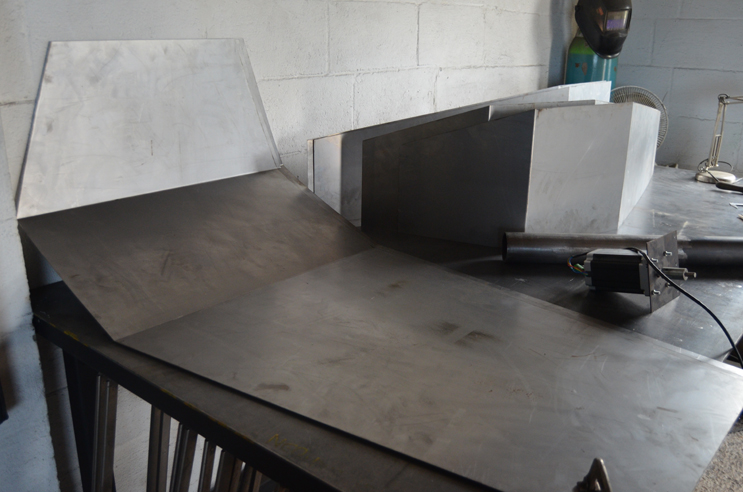
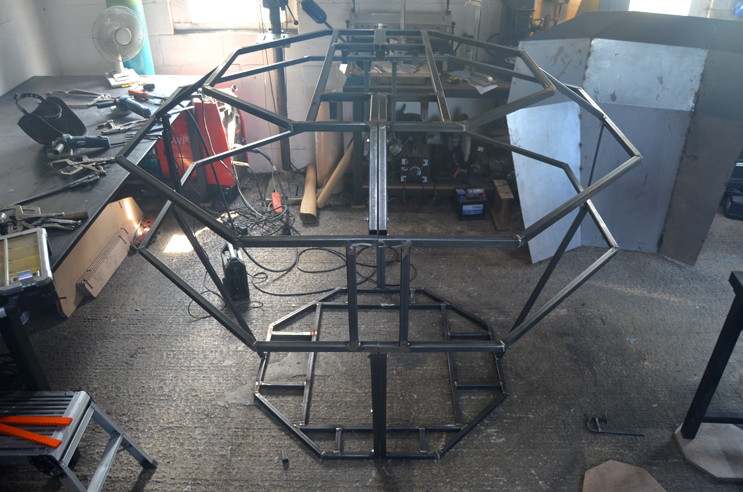
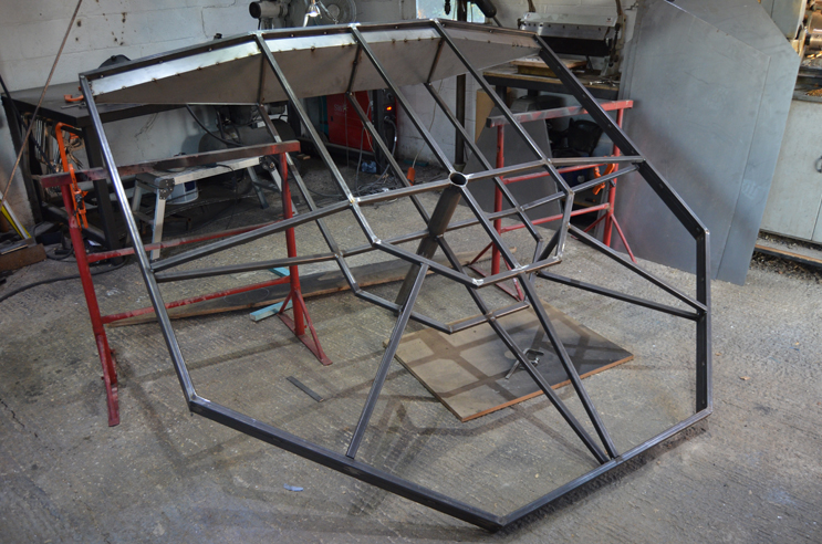
The frames for the body and head were made of 25mm square box section, to which the 1mm steel sheet was then welded. All of the sheet joins had body filler along the inside to keep the rain out.
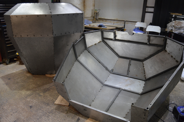
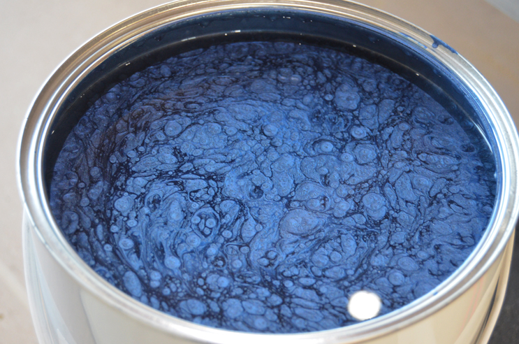
The project needed a surprising amount of paint. I mostly used hammer effect paint (through a spraygun), to help hide the inevitable touching up required as the robot braves the elements.
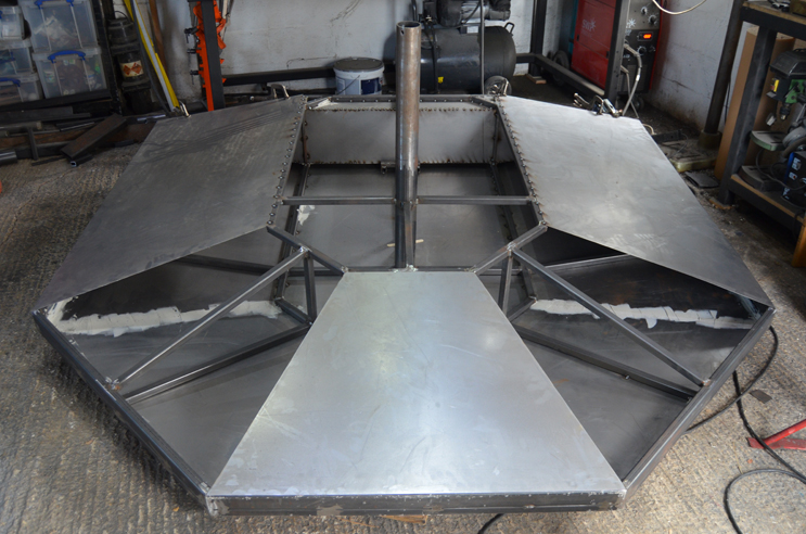
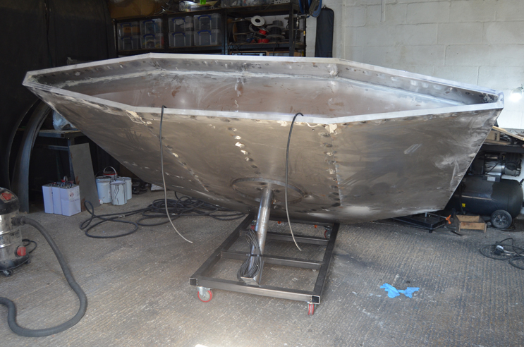
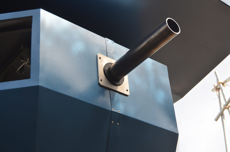
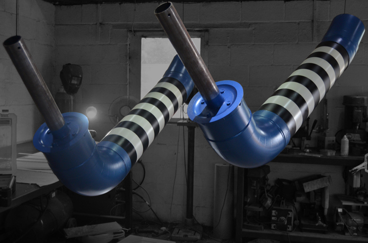
Once the two halves of the body were bolted onto the central frame, a 50mm strip was riveted across the join, with a generous splurge of silicon to make it waterproof. Rotary shaft seals were added to the 3" neck and arm tubes, to allow them to rotate but keep the rain out.
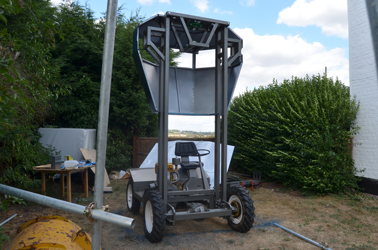
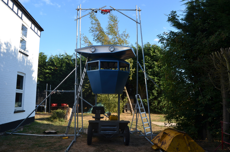
I wasn't going to include this photo as the scaffolding doesn't look very professional, but here it is after all. The head had to be winched above the robot enough for the 600mm neck pole to clear, so the crane is about 6m high. The dumper was then driven into place, and the left / right position fine tuned by inflating / deflating tyres. I was relieved when the neck tube slid into the bearings.
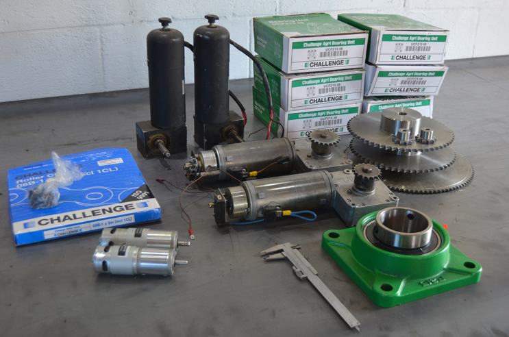
To keep things simple I only used 5 motors in the whole robot, as there was only 8 weeks to make the whole thing.
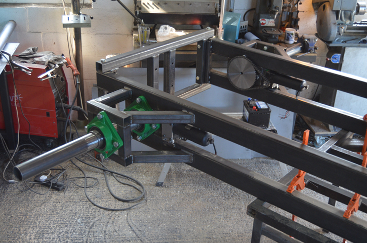
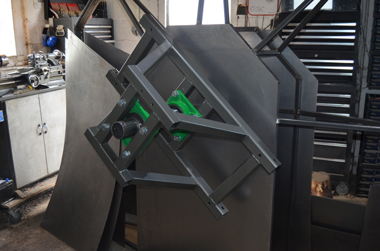
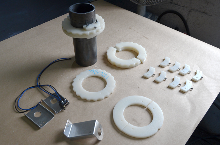
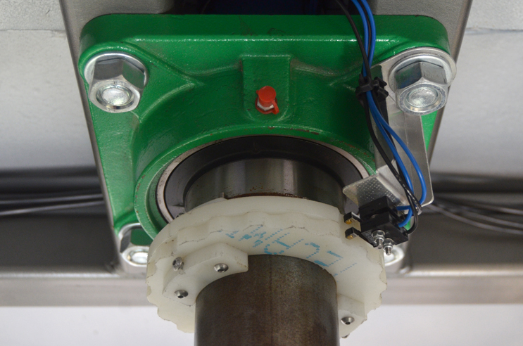
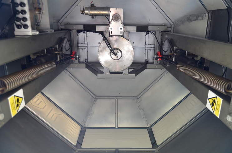
The head and arms had positional feedback via nylon cams. One cam in each pair had a single notch as a home position, the other had 20 notches to measure distance travelled. So, for example, an arm could be programmed to move forward 4 notches, and then return until the home position notch was detected. Along with PWM ramping of speed, this worked very well.
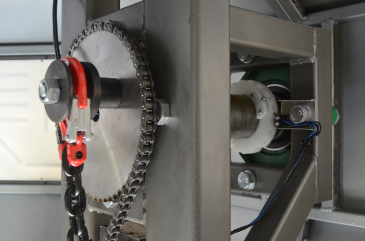
The head and arms were driven via sprockets and chains, but each arm also had a big spring that worked as a counterbalance. The springs are each around 500 x 65mm, and came off a combine harvester.
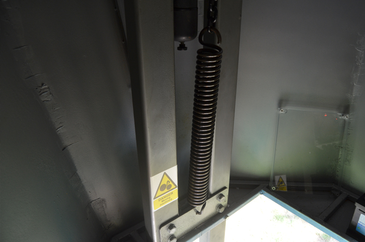
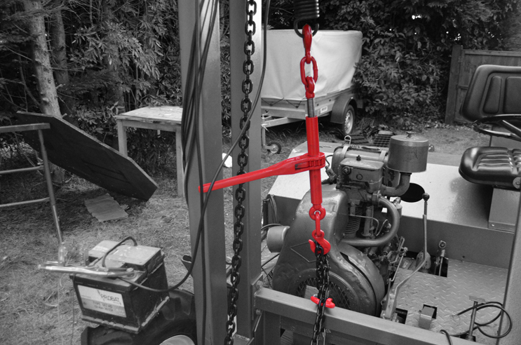
Each spring was pulled tight and attached while the corresponding arm was raised vertically, so that when the arm was forced down the spring was stretched, storing energy to help the motor with the ascent. The spring was linked to the sprocket using a chain with a hook, and the tension fine tuned by cutting off one link at a time until the motor could rotate the arm 360° without too much difficulty. A ratchet load tensioner was used to initially stretch the spring.
The control electronics consisted of a couple of Arduino pro minis, a few relays, and some FETs. The relays controlled motor direction by reversing the polarity, and the FETs allowed control of the speed.
The first test of the head motor caused the control box to emit smoke. I then realised I'd left a clamp on the sprocket while leaning a ladder on the head - it worked much better without the clamp!
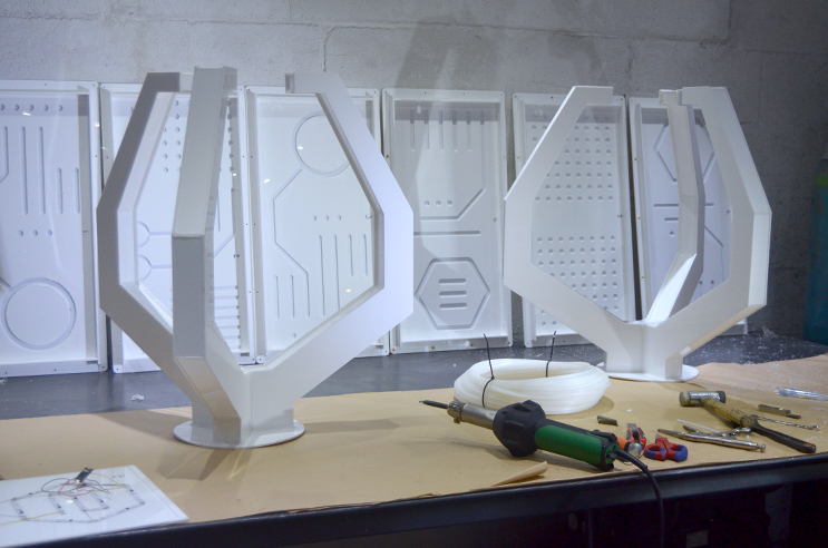
The hands and LED chest panels were made of welded polypropylene
The arms were made of 225mm diameter PVC ducting
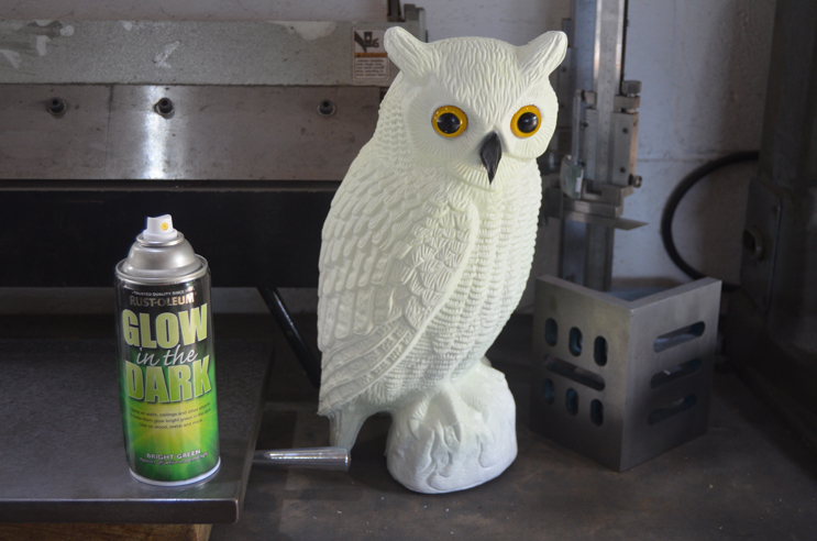
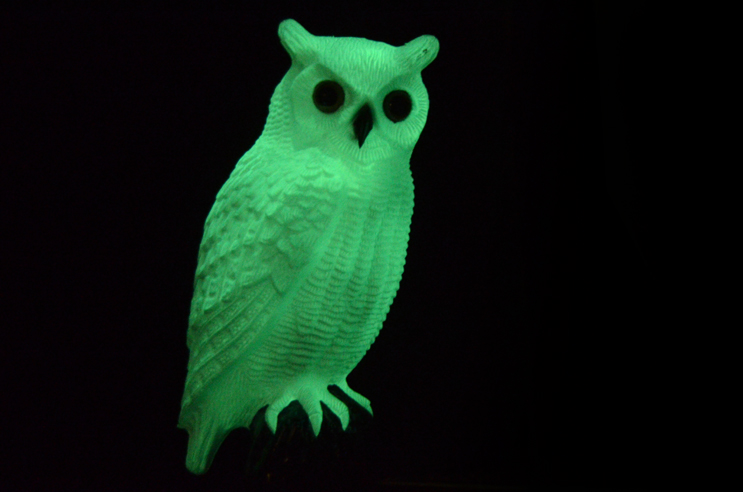
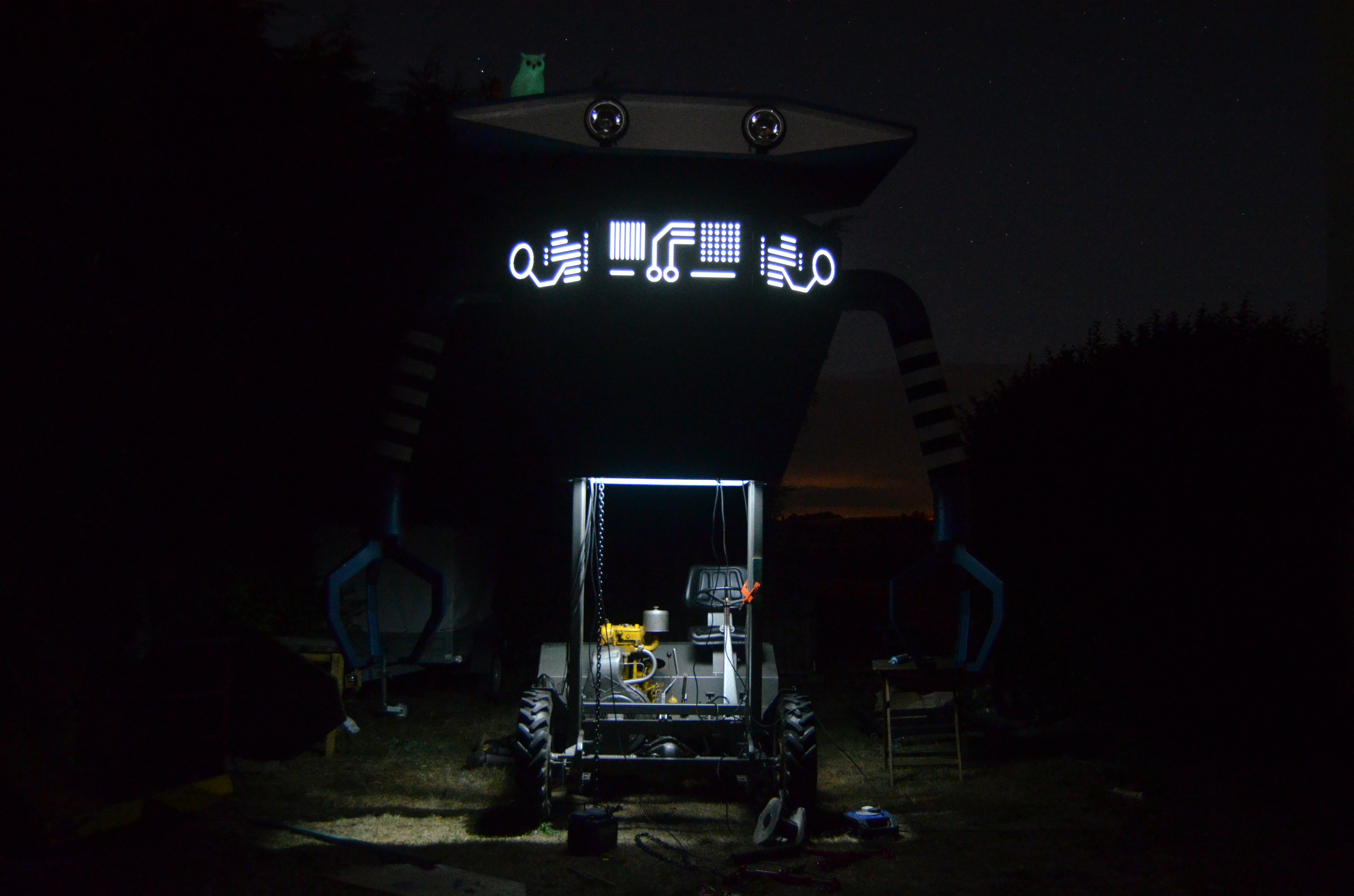
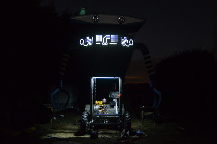
The Glowl
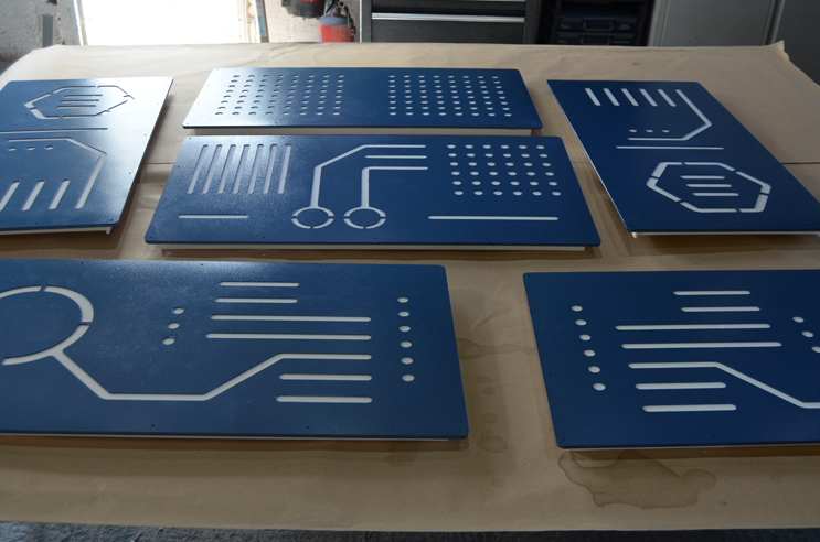
The chest panels were machined down to 0.7mm where the LEDs shone through, and then had an additional painted 1.5mm sheet over the top.
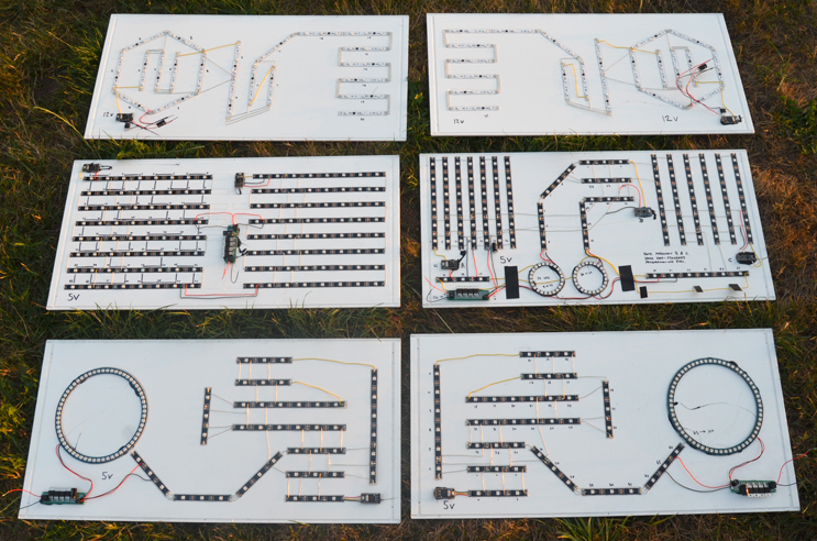
There wasn't much time to wire up the LED strip - it wasn't very neat, but worked fine. The central rear panel had two 8 x 8 grids, one running Conway's Game of Life, the other with a trail of LEDs describing a Hilbert curve.
I think this might be my favourite photo from the whole project - big version here
The head had a bracket on top to which a 1W RGB laser could be attached
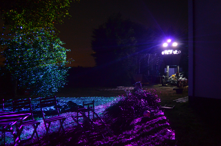
The deadline for this project was our annual summer party, which was attended by a wonderful crowd of friends. The sun set as Charlie Draper treated us to a theremin performance with robot backdrop. Later there was a long synth jam led by Sam Battle of Look Mum No Computer, involving theremin, modular, 808 and Korg Delta.
Can't wait for next year's party...